Sample FGP-Modbus Read/Write Binary Value Example
Description
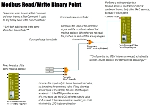
This FGP shows how to read a Modbus point, compare it to a value in the ASIC/2, and Write it to the Modbus device only when the command value is different.
Image

Sequence of Operation
The Modbus point will be monitored on a regular basis, and compared to the command value, held in the ASIC/2 controller. When the value in the Modbus device differs from the command value in the ASIC/2, the command value from the ASIC/2 will be written to the Modbus device until the monitored value matches the command value again. At that point, the write operation will cease, to eliminate unnecessary traffic on the Modbus communication link.
Table of Objects and Published Points
- 2 Modbus Master Objects
- 2 Logic Objects


Tuning/Deployment Help
The two MBM Objects need to be modified with the actual address information you will be using. Adjust the Device Address attribute to match the physical address of the Modbus RTU slave device. Adjust the Start Address to match the parameter address of the Modbus point.
This example uses the Modbus Function to read and write to a register. Depending on the manufacturer, binary information can be stored in a Coil or a Register. Adjust the Function as needed.
Adjust the Transmit Interval as needed to maximize and balance communication on the Modbus link.
Adjust the Handle A Constant and Handle B Constant of the Comparator as needed. If the command value in the controller exactly matches the monitored value in the Modbus device, you can safely remove the Comparator.
