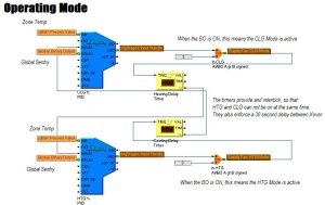
Sample FGP-Constant Volume Mode
Description
This FGP will decide the operation mode of a constant volume piece of equipment. This equipment is typically an AHU or a RTU, but it could also be used on a FCU or any equipment that uses Zone Temp as a controlling input source.
It may also be possible to use this FGP in a situation where the control input source is a Return Air Temp sensor.
The FGP contains two PID objects, one for cooling and one for heating. The two PIDs are interlocked with two Timers. These Timers serve to provide an interlock between each mode of operation. If the cooling PID is active, the heating PID is locked out, and vice versa.
The Timers also serve to provide a time delay between switching modes.
There are two Logic Objects that serve to display a binary indication of when either mode is active. If neither of these two Logics have the BO turned on, it means you are in the Deadband mode.
In this application you can not use the Binary Output of the PID to achieve the function of the Logic Objects. The BO of a PID is turned on whenever the PID is active, regardless of what the analog output is.
Image

Sequence of Operation
The [Zone Temp/Return Temp] sensor will be used to determine the operating mode of the system through two independent PI loops. There will be one PI loop for the cooling mode, and one for the heating mode. Each loop will compare the [Zone Temp/Return Temp] to its respective setpoint, and calculate a 0-100% requirement. The PI loops will be interlocked, so that a cooling and heating requirement can not be present at the same time. A time delay period of [15] seconds (adjustable) will be enforced to prevent rapid changeover between the modes.
Table of Objects and Published Points
- 2 PID Objects
- 2 Timer Objects
- 2 Logic Objects


Tuning Help
To provide a longer delay between changeover, increase the Timing Duaration in both of the Timers.
The two PID Objects are configured for a zone temp application. If you use this FGP with a return air temp sensor, you may have to adjust the PID tuning parameters.
